Introduction
By advancing the understanding of how gravity works from Newton to Einstein to autonomous matter using the "fields do not exist" method applied from brute force analysis it is possible to engineer an apparatus and method that emulates how the Gravitron in atoms shown in the diagram below as T4 generates gravitational force. This apparatus and method is called the Collision Drive. The gravitational force generated indicated as the Gravitron is the Graviton or "Higgs Boson" and the mechanism replicates and generates a gravitational force at T4 that can be pointed in any direction to create propulsive force.
What is the internal motive force used by atoms and subatomic particles? This force is proposed to be created by the behaviour of particles T1, T2, T3 and the force they exert T4 as shown in the diagram below. This force is generated mechanically and ascribed to mechanical engineering not fields. To provide evidence of this the Collision Drive reverse engineers this process to generate this same internal form of movement as propulsion.
 |
The Collision Drive uses Mechanical Engineering to emulate the force at T4 creating what can be referred to as entry level or tier 1 gravitational force Using the "fields do not exist" hypothesis (FDNEH) allows us to identify that an atom is an "autonomous vehicle" or mobile building block capable of moving itself independently in 3 dimensions and function interactively with other particles to, at a minimum, construct and deconstruct matter. Atoms are expected to have the ability to negotiate inertia and mobility with motive force derived from mass energy equivalence. This mobility and interactive nature of autonomous matter gives rise to specific laws of physics determined by and between the particles themselves. The consequence of this interaction is that rules of engagement arise between particles, essentially this means that laws of physics are not fixed as is commonly believed by modern day science. A C-Drive offers empirical evidence for how this mobility is achieved. |
 |
Both the magnet on the left and the earth and moon on the right are not floating on any medium or levitating as a result of "fields" , or geodesics, or lines of force which are believed to cause Space-Time (though useful to make inferences these are completely imaginary constructs or "field-effects") but as a result of real independent mechanical processes in their atomic structures. Understanding these mechanisms and how they work led to successful replication and design of the Collision Drive. |
Note that the movement of particles dipping into and out of the atom to create changes in polarity that generate a nucleus tends to distort orbits or the shell of atoms creating what can be described as a dimple at T3. This dimple will vary in size and shape depending on how the particles are exerting motive force to manipulate the independent movement of each individual atom. Empirical evidence that this interpretation is accurate may be offered by MRI scans of actual atoms.
When the FDNEH is applied to quantum mechanics, the inference is that the "fields" or energy bands do not keep electrons (Trons) in orbit, but rather causes them to constantly cycle (collapse) into and out of the nucleus. This process or cycle is critical. This is the aspect of quantum mechanics applied to gravity. The energy bands have 3 stages T1, T2, T3 which result in a gravitational force T4. T1,T2 and T3 create the tell tale "Heart Shaped Signature" that signals the presence of an active gravitational force T4. The signature may seem arbitrary, but it is hugely important in this process and structure of an atom. The signature is the method by which gravity is created while the particle or "Tron" is the apparatus. It does not matter what substance is used if the signature is the method applied to it, it will generate T4, i.e., a gravitational force. For instance, the collider arms of a collision drive can be seen to apply the signature, the C-Drive consequently generates a gravitational force. If the collider arms are replaced by a liquid, sound/air, solid, gas, electrons etc. - the substance doesn't really matter, it will generate gravity. Even particles of any kind that apply this signature will generate gravity, recognizing this signature is the method by which gravity is created by any apparatus or substance necessitated the signature be covered by the 2nd Patent.
Its worth noting that since quantum energy bands are fields as far as FDNEH is concerned they cannot be responsible for the direction, nature of orbitals, quantity and movement of elec[trons], as a field effect they can only appear to be. This infers that elec[tron] orbits are not determined by "quanta" but by intelligence. This intelligence is presumed to be part of an atom's structure which requires atoms to be viewed as behaving like quantum processors. See Why does a simple material like a grain of salt need 1.32x10¹⁹ qubits?
How the FDNEH reconciles Quantum Loop Gravity (QLG) and General Relativity
In order to do this it is important to first dismiss the existence of fields as is required by the FDNEH.
Once fields (Space-Time Geometry) are dismissed from General Relativity gravity is no longer background dependent. This allows atoms to move autonomously or independently. Atoms swarm and navigate harmoniously using handshakes. The fact that matter appears to follow a Space-Time geometry or curvature when it moves autonomously (swarms) creates what the FDNEH refers to as a "field effect" which is not evidence a field is present since a field effect is an illusion. Fields must also be dismissed from QLG. If the "quantum loop" is redefined as the collapse of the Tron looping into and looping out of the nucleus, which generates a gravitational force (T4) which an atom can use to move itself in any direction, the FDNEH-loop quantum-gravity (FDNEH-LQG) can be reconciled with Einstein's gravity in General Relativity, with the understanding that in both systems the "geometry" is created by the movement of autonomous matter with no background dependency. The intelligent autonomous movement is gravity, it creates the geometry as a by-product, the geometry does not create gravity since technically, it does not exist.
Using this very simple approach the FDNEH quite easily reconciles QLG and General Relativity. See the slingshot animation below to visualize the process.
The slingshot animation shows that autonomous matter is able to curve around an object as though it is in a gravitational "field" or "Space-Time Geometry" when no such background, field or geometry exists. Similarly, when "fields" are dismissed from QLG, gravity is created by the autonomous movement of matter. In essence using the FDNEH there is absolutely no difference between quantum gravity and gravity according to Einstein's General Relativity.
 | |
| Heart Shaped Gravitational Signature The orbiting electron shown in blue, when observed will appear to simply have a circular orbit the loop into the nucleus will not be readily evident In this hypothesis Trons collapse (loop) into the atom from the outer orbit, where they create a nucleus, then exit the nucleus looping back into external orbit. Trons will constantly exchange places during this process such that when atoms are observed it will appear as though electrons, protons and neutrons permanently occupy separate sections, the outer orbits of electrons will also tend to appear continuous when in fact not. Using this process atoms gain mobility, are autonomous and are able to swarm, this ability to control their movement and position themselves is gravity. This means that technically, the incongruencies between classical gravity, General Relativity and quantum gravity can be better understood. As Trons cycle into the nucleus they will experience a cycle with a reduced radius and an increase in acceleration which will cause an increase in mass, offering an explanation for why the nucleus is dense and heavier. If the increase in the rate of acceleration is greater than the speed of light this will mean that they are capable of slipstreaming, which will give the nucleus unusual properties. Once particles begin to slipstream, not only are they hypothetically able to move between adjacent universes (Cx-N and Cx+N) at speeds lower than the speed of light, they are also able to defy normal properties and principles associated with mass and therefore are capable of manipulating what is understood as gravity. Technically, once the FDNEH dismisses fields there is no difference between gravity and electricity, this means that gravity, electromagnetism, the weak force and strong force are all just gravity. It also means that the nucleus should not be viewed as a static mass but as a gateway or nexus for Trons passing through it. |
 |
The image in blue on the right is an MRI scan of an atom. The dimple in the atom which can vary in depth and width corresponds with "Trons"dipping into and out of T1-T3-T2 orbits. Variations in location and size of the dimple imply vectoring where the velocity of the atom is manipulated at T4 making it able to move itself in 3-dimensions, in any direction with incredible dexterity and maneuverability. T4 is a field effect. Mass energy equivalence observed in matter will likely determine the force each atom has at its disposal with which to apply this interactive mobility and autonomous behaviour. The scan is 3 dimensional and it fits what is predicted by T1-T3-T2. These dimples on the surface of atoms are likely to be indicative of the automobile nature of autonomous matter. The entry and exit of electrons from the shell exchanging positions into and out of the nucleus is unlikely to be visible and the.shell and nucleus may appear intact. However, this activity implies that atoms are not perfectly round or will show pathways between the nucleus and the shell. Technically this implies singular "Trons" (can generate the nucleus and shell of the atom) as they become an electron, neutron or proton depending on where the Tron is located on its orbital path that moves the atom or maintains its position using gravitational force. see Magnetic resonance imaging of single atoms on a surface. Atoms and therefore matter in general navigates intelligently |
 |
| An atom, which is inherently a tiny vehicle is able to move itself and matter or objects comprised of atoms are able to swarm, that is, create dense matter and navigate intelligently around each other. The FDNEH offers autonomous matter as the explanation for gravity. To our more primitive mind, primordial science or untrained eye a body such as a meteor or satellite approaching a planet and making a sling-shot maneuvre away shown above, we see this movement as being caused by the blue line. This imaginary blue line becomes a "field" to which we attribute gravitational force, geodesics, Space-Time and so on. This blue line or "field" can also be demonstrated to students on rubber or spandex using a heavy object and marbles. However, using the "fields do not exist" approach, to the trained eye that observes this movement the "field" does not exist, rather the red-line vector demonstrates the atoms of which the two objects consist negotiate how to position themselves relative to one another and use the internal autonomous mobility within their atoms to navigate and determine exactly how they pass one another. This same process is applied to Archimede's bouyancy and the example of a cup resting on a table and applies to both stationary and moving objects . The redline vector in the animtion illustrates the active "handshake" initiated between the two bodies of autonomous matter as they come into close "physical" proximity. The information shared in the handshake determines how the atoms in each body propel mass consequently the two bodies navigate around one another. This being the case implies that the blue line or "field"which is currently thought to be Space-Time curvature does not exist, it is a figment of the imagination, imaginary friend or construct that though fictional can be useful to explain how the two bodies interact. However, this is fine as long as physicists comprehend the limitations of using fields, the blue line, spandex or Space-Time curvature to explain gravity and understand how this is a more primitive approach to understanding how the universe works and consequently will not be misled into making incorrect interpretations of observations and the mathematics used to explain them. |
The movement or rotation of particles or mass, changes in polarity within an energy band or harness that generate the gravitational force that moves atoms are reverse engineered to create a collision drive. The diagram below shows direction of force at T4.
 |
Just like a jet engine, rocket, plasma and ionic thrust the C-Drive generates propulsive force internally. However, unlike the other propulsion systems it does not generate exhaust of any kind and can operate in a vacuum. Therefore, it can propel a vehicle in diverse environments e.g. on the ground, under water, in the air and in space. The thrust it is capable of generating can exceed the propulsion systems mentioned. |
Materials and motors at hand were put together to create the collision drive. When rotated the collision drive generates a force that mimics or replicates gravitational force T4 and consequently this drives the mechanism forward or in any direction. To see the results of tests on the Collision drive click here. To see the collision drive in action click the video below:
Although billions of dollars have been poured into projects and the sciences to try to understand gravity and hundreds of thousands of man hours have been spent on labs and research in the highest echelons of tertiary education around the world to unravel how it works these efforts have thus far failed to fully understand gravity or yield a simple device that demonstrates or generates gravitational force.

Unpacking the Science of a Collision Drive
 |
C-Drive with rectangular and circular weights attached to collider arms |
How the C-Drive works.
 |
How the C-Drive Generates Propulsive ForceThe Impossible Machine: The advantage of a C-Drive throwing its mass into the harness and making impact with it twice per revolution is that the process is simple enough for even a layperson with no background in mechanical engineering or physics to see and understand how it generates propulsive force.You don't need to be an expert to appreciate the technology is pragmatic, simple and genuine. This makes it easier for an expert to convince a layperson it works. The interesting aspect of this device is that if you did not see the technical design animated above you would have been told its not possible to design. This is the most advanced propulsion system and if you understand it from the animation above you deserve a pat on the back. You now understand the mechanics of gravitational force and how it is able to function or operate without the need for a "field" (i.e. a fluid, medium, geodesic etc). See the animation actually working in the proof of concept video clip. The animation above shows continuous mass flow moving like a jet stream in a net direction depicted by the blue vector arrows. The independent sliding action of the collider arms continuously hurls the mass forward and the coupling captures this propulsive force making it "push" the circular harness twice, inside the the front of the harness and outside the back of the harness depicted by the blue arrows. This generates propulsion in a net direction through 360 degrees of rotation. Mass is attached to the arms to increase the mass flow rate. |
 | |
How C-Drives are designed to rotate and generate thrust in one direction, without violating Newton's 3rd Law of MotionChanges in polarity of the collider arm ensure propulsion remains in a net direction through 360 degrees of rotation. The net force moves in one direction. There is no backward acting propulsive force due to continuously alternating polarity every half rotation. It provides a solution to the problem concerning Newton's 3rd Law of motion that states that "for every action (force) in nature there is an equal and opposite reaction." By the collider arm alternating polarity mechanically in relation to the head of the mass turbine this law is not violated and propulsive force is maintained in a net direction. This continuous flow or thrust created by mechanically engineered means with zero emissions is referred to as Tier 1 Gravity, i.e. an internal [independent] gravitational force generated using mechanical engineering. The engineering of an alternating mechanical polarity is a mechanical solution similar to how a commutator in an electric motor consistently reverses the direction of current such that it allows a motor to keep turning in the same direction. By the commutator in an electric motor reversing the direction of current every time the coil passes a vertical position or every half rotation, an electric motor is made to rotate in a net direction. Similarly, by the collider arm (interacting with the interior and exterior of the circular harness or wing) and reversing mechanical polarity with the head of the mass turbine every half rotation (180 degrees), shown in the animation above, the direction of propulsive force in the C-Drive is exerted in a net direction comparable to the continuous unidirectional mass flow seen in rockets and jet engines.Consequently, the C-Drive is able to rotate and generate thrust in a net direction throughout 360 degrees of rotation, which generates thrust by creating a Static Recycled Mass Flow (SRMF). Its worth noting that if Newton's Third Law could not be manipulated by changes in polarity to generate force, thrust or turning motion in a net direction, a simple electric motor would not work. The C-Drive, like an electric motor, uses mechanical or material polarity to generate thrust continuously in a net direction. What is note worthy and may need to be identified is that physical, matter like electric current, has inherent polarity as demonstrated by the collider arm shown sliding back and forth over the mass turbine. |
Navigation for Collision Drives

C-Drives navigate by vectoring or altering the net direction of force |
The animation underscores just how quickly vehicles propelled by C-Drives can change direction and accelerate by advancing the mass turbine from a gentle feather-light position to aggressive maximum force.
The mass turbine constantly shifts and alternates the collider arm and its load's centre of mass using changes in polarity to generate force in a net direction, while the circular harness or wing converts the force and impact from collisions into propulsion.The collider arm swings into the circular harness concentrating its force like a battering ram toward the mass turbine's position, however, the severity of its impact is controlled by the curvature of the wing, allowing the impact of the propulsive force to be cushioned by the parabolic nature by which the coupling interacts with the circular harness as it guides the collider arm around it.
When the mass turbine is in the centre of the circular harness the C-Drive is in neutral and will not exert propulsive force in any direction. However, in neutral the C-Drive can be spun up to very high rpm very quickly and launched rapidly in any direction the mass turbine is pointed with significant acceleration.
The bar showing gentle to aggressive shows that, even if the rpm remains constant, the amount of propulsive force that can be applied is adjustable. It can move with gentle, feather-light movement or launch aggressively into very rapid acceleration. This coupled with the fact that it can be pointed in any direction makes the C-Drive highly maneuverable.
C-Drives can rapidly change direction and move with significant propulsive force in any direction that the mass turbine and drive shaft are pointed (i.e. toward any section of the rim of the circular harness).
More than one C-Drive arm rotating in the same direction but out of phase or in the opposite direction is required to cancel out non-conducive vectors and fine tune propulsive force.
C-Drives navigate by displacing the mass turbine from the centre of the circular harness in the direction where force from collisions is required to be vectored. The animation demonstrates this. The sliding action of the mass turbine is able to create a re-cycled or static recycled mass flow.
Gravity Assist (GA)
 |


C-Drives can use g-forces to brake to a stand still, change or reverse direction on a dime, with remarkable agility and accelerate faster in the same direction. Not only is the Collider Arm always within striking distance (AWSD) of the Wing or Circular Harness, acceleration is further amplified by g-forces from the moving vehicle due to principles of moments the Collider Arm experiences as it rotates around the Mass Turbine. G-forces can be converted into propulsive force. Cornering, braking, banking and turning any condition in which g-forces are created that increase the mass of the collider arms can be converted into increased impact from collisions into the wing or circular harness and therefore induce acceleration in a vehicle as illustrated above. As a consequence craft propelled by C-Drives will make 180 degree reversal of direction, 90 degree or right angle turns instantly with unusual agility, this is due to the fact that rather than being burdened by g-forces during sharp changes in direction, the C-Drive uses principles of moments to harvest these forces in a manner that accelerates rather than hinders their movement during turns giving them exceptional agility. Rather than being subject to g-forces like a conventional aircraft, a C-Drive will be able to manipulate g-forces and apply them to its movement. It allows C-Drives to move back and forth, instantly change direction, make corners and mmaneuvers that would otherwise seem impossible- for instance jet aircraft usually have to bank when turning, they can not make a perfect right angle, 90 degree turn at speed, C-Drives should be able to do this. How these very high performance flight characteristics, such as right angle turns and 180 degree reversal of direction are achieved had no previous explanation. However, the explanation provided above shows how this unusual kind of flight can be achieved even by a Tier 1 gravity propulsion system deployed in a C-Drive. When a car needs to make a sharp turn on high-way an embankment is raised where the road curves. The support of the embankment allows the car to make a sharp turn at high speed, the embankment supplies the resistance the vehicle needs to safely turn. A C-Drive on the other hand will not need an embankment due the fact that it is able to generate the same resistance required for the sharp turn within the C-Drive mechanism itself, as long as the structure of the vehicle can withstand this manipulation of g-forces. C-Drives can exit earth, head into orbit or space and apply Braking Assist for a cold re-entry back into earth's atmosphere all the way to the destination. Once outside earth's atmosphere C-Drives can exploit extremely high velocities, before decelerating to descend back into the atmosphere for cold re-entry. For long journeys, C-Drives will use Braking Assist to accelerate half the way to the destination and decelerate the other half until it arrives. It can accelerate to the halfway mark at 1G and decelerate the remainder of the journey at 1G saving fuel, and creating a comfortable journey for passengers and crew. How C-Drives internally neutralize G-Forces Though passengers in C-Drive vehicles will experience g-forces (due to being a Tier 1 or mechanical form of Gravity device), the fact C-Drives themselves are unaffected by g-forces as shown above is important to note (for instance, during Brake Assist, the C-Drive is decompressing mass accumulated from g-forces and converting it into forward momentum or movement consequently internally neutralizing the effect of g-forces). The explanation above shows that C-Drives even neutralize g-forces from acceleration in a straight line (G-Force Assist) by decompressing momentum (the accumulation of mass) and converting it into velocity. Decompression can be described as a form of mechanically induced anti-gravity that works by cancelling gravity or g-forces by harnessing the same gravity or g-force and using it to counter itself by redirecting and pointing it in an opposite or alternate direction, as is seen with Gravity Assist (GA), Braking Assist (BrA) and G-Force Assist (G-FA). If the cancellation is equal and opposite the net effect is the object or vessel coming to a stand-still where it remains suspended in place and may experience zero gravity. For example, when a car, rocket, airplane or jet accelerates, the driver, pilot or passengers are pushed back into their seats as a result of g-forces. G-forces can be a major disadvantage to quick and rapid travel. The ability to understand how to neutralize them is priceless. C-Drives show how this can be achieved as is illustrated in the animated explanation. Though this g-force neutrality only occurs within the mechanical functions of the C-Drive due to it being a form of Tier 1 Gravity, when the very same process is applied at the atomic level using higher Tiers of Gravity the result is the same. In other words the process by which vehicles can move without creating g-forces that negatively affect vehicles, their goods and occupants can be better understood. |


The Boss C-Drive, 16x the Force


 |
| Boss Drive full compliment |
 |
| Massive Boss C-Drives for enhancing power generation Boss C Drives of this scale can be manufactured and assembled locally. |
 |
C-Drives can use Gravity Assist to Boost or Amplify an input Force Since proportionally less force is required to lift the mass or weight in C-Drives this is like having a shaft depth or height that is infinite with a "load-advantage" that is constantly falling. What is lost in exchange is propulsive force, which is instead converted into torque that drives a generator boosted by gravity assist. Renewable energy Tests show that electricity generated by gravity assist is the cheapest form of electricity generation in the world. C-Drives can "turbo-boost" or amplify force by using gravity assist. See the SRMF animation below. |


 |
Give me a lever and place to stand, and I will move the earth - Archimedes The C-Drive above simulates "Conservation of [Mechanical] Advantage" from X>Y to X'>Y' it is an advancement from "Conservation of Momentum" and "Conservation of Energy". It shows that, like the two types of conservation, Amplification of force or energy is a principle or law in and of itself. It is possible, not as over unity, but within the laws of physics, when it is understood that the advantage gained is due to the conversion of force from propulsion (lift/thrust) to torque made possible by anchoring the device while alternating mechanical polarity every half rotation. It also helps explain some of the merits of understanding how gravity works. As the load is lifted it gets lighter (Y and Y'), as the load drops it gets heavier (X and X') .i.e. only 10% of the effort is required to do 100% of the work. Furthermore, when this is done in X-Formation (45 degrees) there is the additional advantage of Gravity Assist.. Though easily unseen 90% of gravitational lift/thrust is sacrificed in exchange for the gain. |
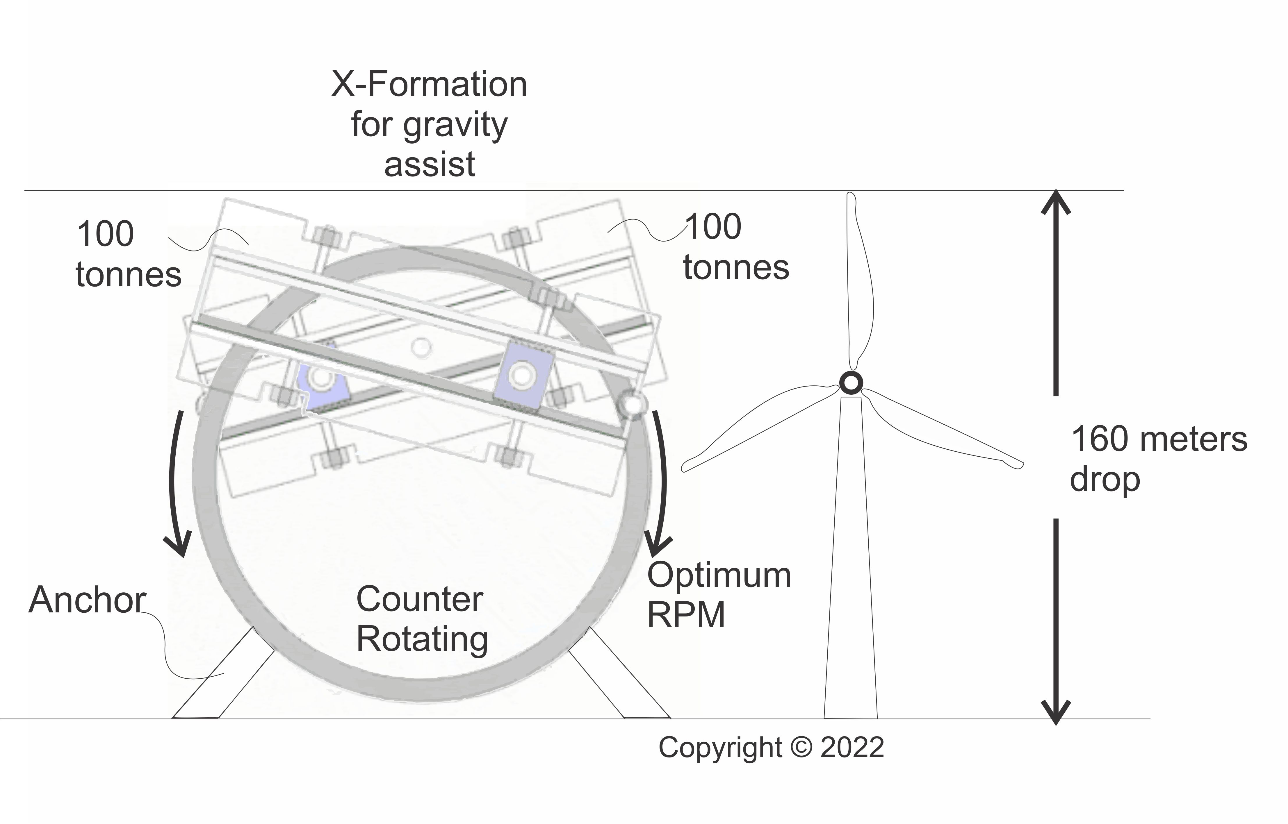 at 1 - 5 rpm per minute. Since it uses a cheap material like concrete and uses HD-SRMF, it would not require, wind, water etc to operate creating a low cost source of renewable power generation and storage with a significant profit margin for power utility and distribution companies. Anchored power generation C-Drives would need to be paired for counter rotation to stop propulsion and convert it into torque. An installation of this size could easily have collider arms weighing 100 tonnes each. This would provide a 200 tonne drop from 160 meters with each rotation. A small motor would induce a minimal 10% turning force during each drop to ensure each rotation reaches a minimum rate of acceleration that returns the collider arm to the Apex position for continuous power generation or storage. 200 tonnes of continuously falling mass multiplied by the rate of acceleration due to gravity would be comparable to the water mass generated by a hydroelectric dam that could conveniently be situated anywhere. |
 Its difficult to imagine a 200 tonne mass moving or rising off the ground. However, the C-Drive is primarily a propulsion system, the mass is of no consequence when subjected to a relevant rpm, it will generate lift proportionate to its mass and rpm. The mass and size of the C-drive will not prevent it creating lift and thrust. The propulsive force generated by collider arms carrying a 200 tonne load would be so great that it only makes sense to use two counter rotating C-Drives to push or pull against one another to cancel out propulsion and redirect it into torque with which to drive generators. |
- When the 200 tonnes falls from the Apex position, it doesn't just fall, it also exerts principles of moments around the drive shaft, making it able to increase torque.
- Since the C-Drive is anchored and prevented from moving, as much as 90% of propulsive force is converted into torque, which boosts or amplifies the generation of electrical energy (see section shaded in blue).
- When the mass attached to the arm falls it is accelerated by gravity assist.
- In the cycles where the C-Drive rotates upward, the collider arm rotates the mass horizontally more than vertically reducing the effort required to reach the apex storage position and optimal rpm.
- The rotation cycle feeds into the next cycle conserving energy through each cycle of rotation.
- Once it is in Apex energy storage position, the C-Drive can store this energy for very long periods, until it is required.
- As long as there is a residual charge for the power charging phase to induce acceleration that maintains optimum rotation speeds from Apex to Apex energy storage positions, the C-Drive can supply cheap electricity indefinitely, making it cost effective for suppliers and distributors of electricity.
- A 160x160x40meters C-Drive may take up the space of 1 wind turbine, yet when the collider arms and their 200 tonne load falls they can generate renewable energy equal to a large hydro-electric power station.(Building a C-Drive power station is of course many times cheaper than building a huge hydro-electric dam such as 3 Gorges or the Grand Coulee, yet it can potentially generate more electricity than installations such as these.)
- The High Density Static Recycled Mass Flow (HD-SRMF) means C-Drives can serve two functions in that they can both store and generate electrical energy. HD-SRMF possibly offers the cheapest, and most practical method for storage and generation of electricity available today. There is control of both the the mass flow and the turbine.
- C-Drives do not need deep mine shafts or cable systems to store and generate power and can therefore be made more compact.

 |
C-Drives will be used for propulsion and to enhance power generation |
 |
Collision Drive |

Amplification of Force from Collisions


The twin collisions in the collision drive depicted in the logos


The answer to this is simple, the colliding arm slides back and forth.
The independent transfer of momentum takes place because for the duration that the
the collider arm (3kg block), makes contact with the harness and vehicle or circular wing (4kg block) the collider arm slides along the drive shaft head (mass turbine) allowing it to push the harness thereby propelling the vehicle independently. At the end of its sliding action any energy it may have left is deployed or harvested by being swung into the impact of the next spin cycle, by then it has changed polarity and repeats the process continuously propelling a vehicle.
Note that the collider arm consists of a single frame to which a heavy mass is attached. Therefore, when it is swung to strike the circular harness (the blue 3 kg block striking the 4 kg) it cannot possibly be moving backward if it is moving forward to strike the circular harness.
In an inelastic collision, when the collider arm (3kg block) strikes the circular harness .i.e. the vehicle (4kg block) the entire mass of the collider arm is travelling with the circular harness in the same way the blue 3 kg block travels with the blue 4 kg block in the animation. When the collision is inelastic, even though the collider arm may appear to move backwards, it's net direction is in fact forward in the direction of net propulsive force.
Whether the collider arm is rotating backwards or forward it exerts its impact with the circular harness and propulsive force in the same net direction. This is why the collider arms can counter rotate yet propel a vehicle in the same direction.
Once a rocket or jet engine emits its burn, that's it, that momentum or impulse cannot be recovered, its force dissipates into the atmosphere with pollutants and/or residue.
On the other hand at each ejection cycle at the end of the length of the collider arm post collisions, where polarity changes, a C-Drive captures any residual momentum by converting it into spin with which to deploy in the next collision making the process potentially more efficient than a jet or rocket engine.

A C-Drive Recycling Mass Flow by moving from Neutral to Launch displaying a B-Ken Maneuver
 C-Drive Force Dampening & Vectoring |
The animation above shows that the direction of rotation or spin does not change the direction in which propulsive force is applied. Using what has been introduced thus far you should be able to explain what the dual collider arms, spinning in alternate directions in the C-Drive animated above are doing. [..and yes, it looks like breast stroke]
 |
Source: Pacra Patent Lift with gravity assist @ 45 degrees: Each down-stroke of the collider arms generates lift with lateral stability and gravity assist. The C-Drive animated above demonstrates a powerful V-TOL lift force. Horizontal forces counteract each other creating lateral stability while the lift force is constantly directed upward in one net direction due to changes in polarity every half rotation - see animation below for explanation. Rather than point the C-Drive directly upward and generate thrust like a rocket (without gravity assist), the example shown above vectors thrust upward at 45 degree angles. Can you explain why? The C-Drive above vectors its thrust using an X-Formation with two collider arms rotating two offset drive shafts. This configuration is not only capable of generating a very powerful upward thrust, it is also able to generate very powerful lateral/horizontal stability for the vehicle being propelled by the C-Drive, which is useful, for example, if there are strong cross winds. It can provide V-TOL capability where the vehicle is suspended motionless just above the ground and launch capability where the vehicle is lifted upward very slowly or at great speed with zero emissions. |
 |
| Source: Pacra Patent C-Drive Heavy Lift Formation: Two Collision drives configured as shown above can have a 75% or more lift advantage over gravity by redirecting gravity and using it to generate lift. To do this the collider arms are split into two axles with the harness configuration using actuators - similar to the manner in which aircraft adjust flaps. Instead of pointing the C-Drives directly upward the direction of force is raised by 45 degrees allowing the striking distance to be constantly heavier on one side as the collider arm strikes the harness the downward pull of gravity increases the upward impact of collisions into the harness. As these collisions transfer momentum into the harness they also reduce the size of the collider arm as it travels upward. This process redirects the downward gravitational pull upward by 45 degrees. Since the two collider arms are pointed upward by 45 degrees the downward pull of gravity on the heavier side of the collider arms is directed upward into the circular harness and they jointly vector a propulsive force upward with gravity assist. In order to gain lift and buoyancy the collision arms must achieve a minimum rpm. This configuration will give the C-Drive an advantage in lifting heavy payloads, even from ground directly into space. Can you explain how this is possible using what you have learned about C-Drives thus far? This is part of understanding how gravitational dynamics work. |
 |
Continuous Thrust: The animation translates the rotational movement of mass from a C-Drive into the linear downward mock blue and purple flame ejected from rocket engines. Though the collider arms generate lift using upward collisions that are inelastic these are re-interpreted as as a downward force such as that from a rocket engine's burn using the blue and purple flame. The blue flame lasts for 0-180 degrees while the purple flame lasts 180-360 degrees. Throughout this period the mass being moved to generate thrust equals the mass moving downward to propel the space shuttle or rocket upward. With each downward stroke the collider arms are exerting an upward propulsive force that thrusts the craft upward. The process is counter-intuitive. The illusion is that the collider arms are moving downwards, when in fact in terms of propulsive motion during the downward stroke they are in fact moving upward. Observing the blue and purple [non]flame emerging from the shuttle engines and propelling it upward summarizes the net forces acting on the shuttle. The impact of C-Drives can be compared to a pulse detonation engine. However, the method of propulsion used by rockets of any kind does not have advantages such as gravity assist, neither do they have built in stabilization through lateral locking, C-Drives also have the added advantage of zero-emissions. Using the method above you can use the much simpler linear mass flow method applied to rockets to calculate the thrust force the collider arms will generate. This method is useful only for purposes of simplification. Assuming that we have a motor with the horsepower or watts that can generate the required rpm/rps, necessary torque and a C-Drive of a build quality that can withstand these immense forces, see if you can calculate the following: If a C-Drive is 1.2 meters in diameter (collider arm travel length). Its collider arms are counter rotating. The attached mass weighs 750 kg in total. They are rotating at 3,000 rpm, can you work out the linear thrust force in Newtons the C-Drive will generate? [Note that 3,000 rpm is 50 rps. In one rotation the distance covered is 2.4 meters, therefore in 50 rps the velocity is 120 m/s and the flow rate is 750 kg/s (Change in mass (∆m)=750 kg, Change in time (∆t)=1s, Velocity (v)=120 m/s Force in Newtons exerted by the collider arms = (∆m/∆t)×v the C-Drive rotates 50 times per second. It has 2 collisions per rotation. This means that the rate of change in mass (∆m) will be 750x(50x2)= 75,000 kg this change in mass (∆m) takes place in 1 second (∆t). the velocity is 120 m/s Force in Newtons = (∆m/∆t)×v = (75,000 kg/1s)x120 m/s = 9m N The result for thrust you find can take place with zero emissions. It should be noted that rocket and jet propulsion does not have the advantage of gravity assist gained from the ability of C-Drives to apply principles of moments to enhance collisions and increase propulsive force. This means that as much as the force in the equation is 9m N, a C-Drive can use principles of moments to amplify this force by as much as 75% or more, this amplification is what is referred to as "gravity assist". It should also be taken into account that the propulsive force generated in the equation is for a C-Drive that is roughly only 1.2 meters in diameter. This entails being able to potentially generate as much 15m N of force from a relatively small device if it is able to satisfy build quality and has a powerplant that can supply the required torque. An advantage of C-Drives is that they can process highly dense materials for mass flow. The word process is being used instead of exhaust because C-Drives have no emissions since they re-cycle mass flow. For instance, in the example above, at only 3,000 rpm* the small C-Drive with diameter of 1.2 meters is processing the equivalent of 75,000 kgs per second of "exhaust" (with zero emissions). In comparison the most powerful rocket ever built to date, the Apollo 11 Saturn V used by NASA between 1963 and 1967, which is many, many times larger than the C-Drive example used here only processed or put out 12,980 Kg per second with exhaust emissions. See the below the comparison between jets/rockets and C-Drives. Theoretically, if the 1.2 meter C-Drive could be rotated at 15,000 rpm* it would be more powerful than Nasa's Apollo Saturn V which generated 35m N. It needed 5 powerful F-1 rocket engines to generate this thrust. At 15,000 rpm just one 1.2 meter diameter C-Drive could generate 45m N (without even having to deploy gravity assist) *Its important to note that in the examples above the rotation of the C-Drive has been converted into a linear mass flow to be able to make the comparison with rockets fair. However, the reality is that in C-Drives the mass flow that feeds collisions is circular (centrifugal and centripetal) not linear. If the conversion is not implemented C-Drives generate exponentially greater force from mass flows than rockets.The impact from the centrifugal and centripetal mass flows into the wing (circular harness) are what generate propulsive force. Without linear conversion  C-Drive: Diameter: 1.2m, Radius (Collider Arm): 0.915 m, Mass 750kg,2 collisions (impacts) per rotation At 3,000 rpm with a 750kg load on the collider arm the C-Drive generates a mass flow with 67m N or 6.9m kg-force Thrust with Collision Theory @ 3,000 rpm the thrust = 135.3m N which is 3.8x more powerful than Saturn 5 At 15,000 rpm with a 750kg load on the collider arm the C-Drive generates a mass flow with 1.7bn N or 172.7m kg-force Thrust with Collision Theory @15,000 rpm the thrust = 3.38bn N which is 96.7x more powerful than Saturn 5 [for the equations see the mathematics of C-Drives]: Note that results for thrust shown above do not include amplification of force. It should also be noted that the C-Drive can generate this thrust with zero emissions.   C-Drives are currently the most powerful and advanced propulsion system, when Tier 1 Gravity maxes out a switch to Tiers 2-5 Gravity is required for faster travel. See the force vector diagram below to understand the basic forces at work.  The C-Drive functions within Newtonian Laws: Every collision that pushes the vehicle creates a reaction force that exits the vehicle as a result of the sliding action of the collider arms. The animation above shows the action and reaction. According to Newton's 3rd Law for every action there is an equal and opposite reaction? How is it that when the collider arms, which are attached to the same vehicle, move upward or collide [the action] they they do not create a downward force [the reaction] that cancels the upward lift force when both are attached to the same vehicle? Is this not a violation of Newton's 3rd Law? No, Newton's 3rd Law applies and remains in tact when the C-Drive works. To answer this question you must first understand how inelastic collisions work. When the collider arm strikes the circular harness [the action] the impact must be inelastic to lift the shuttle or vehicle. Secondly while the shuttle is being lifted by the impact, Newton's equal and opposite law does take place, except that the force of the opposite reaction is absorbed, neutralized, or removed from the vehicle by being diverted through the sliding action of the collider arm. Both action and reaction in Newton's 3rd Law are taking place, however, the action is being allowed to proceed to push the vehicle while the reaction is being absorbed and prevented from stopping the vehicle by the sliding action of the collider arm, which is appropriate physics for an inelastic collision. The reaction, in relation to the vehicle, is like a sprinter on a treadmill exerting maximum effort but remaining static or in the same place, the reaction's momentum is consequently being neutralized and removed from the vehicle allowing it to be attached to and move with the same vehicle without cancelling out net propulsive force. The sliding action therefore neutralizes the force exerted by Newton's opposite reaction allowing the initial action to move the vehicle in one net direction of force though they are mounted on the same vehicle. Since the opposite reaction is isolated, neutralized or rendered static while the arm slides the shuttle has no option but to continually rise in the net direction of Newton's initial action force caused by the impact or collision. Both action and reaction take place. There is no violation of the Law of Conservation of Momentum. Therefore, Newton's Laws of Motion remain intact, there is absolutely no violation and the C-Drive is able to rise. This takes place until at the end of its sliding action when the arm is swung into the next impact with the circular harness. Look at the video clip of the C-Drive in live action, this is how the forward motion of the drive is being created.Also see the 3 kg and 4 kg inelastic collision that create combined velocity shown above. Also see "continuous thrust" above where the forces unleashed by a C-Drive are translated into the action-reaction force of a jet engine or rocket using a blue and purple exhaust or flame. The "Always within striking distance - AWSD (x)" animation clearly shows that as the elongation to constant striking distance x of the collider arm takes place the reaction force is seen clearly stretching from or leaving the vehicle while the action force of the impact is preserved and propels the vehicle in the net direction. These practical and simplified diagrams and animations should help you make informed decisions about the collision drive. See the diagram below to see the net direction of the forces being vectored. Ki - Force Vectoring is a ScienceVector forces acting on the Wing (circle) |
 |
| Source: Pacra Patent C-Drive Force Vectoring: It may be difficult to understand what C-Drives are doing just by seeing them spin. The Force vector chart will help you understand the direction force is being exerted. The vectors in blue and other colours represent vectors from "push" or action forces. The force vector chart for the two counter rotating collision drives when combined shows isolation or locking of lateral or horizontal movement which prevents a vehicle from drifting sideways. Even if an attempt was made to push a vehicle laterally when suspended in the air, this force would have to exceed the force by which the the C-Drive is holding its horizontal position. This will greatly enhance stability of V-TOL. It is unlikely that there is any kind of conventional air based V-TOL technology being used or currently in development that can rival C-Drive V-TOL technology. The remaining arrows show a net direction of propulsive force moving upward. The four elongated arrows created by X-Formation of the position of the collider arms show that maximum impact from the collider arms and the weights attached to them is vectored at 45 degrees. Collision drives show the potential of having V-TOL capabilities unrivaled by any kind of aircraft or propulsion system currently in use.The uncanny stability and ability to maintain position and lift expected in C-Drive propulsion applied to vehicles is best compared to magnetic levitation (maglev) rather than air based methods of propulsion.The Force Vectoring Chart above shows how C-Drives will be able to remain perfectly still in mid air, even as low as 30cm above the ground without displacing any air for purposes of lift or thrust. This configuration exploits gravity assist during lift. The X-Formation can also be used for safer more powerful launches from ground directly into space. The chart above is useful for engineers as it enables them to predict the direction in which the C-Drive configuration will exert force and therefore lift or thrust. |
 |
I to X-Formation Vector Map of Reaction Forces: being adjusted by actuation. Reaction forces in red and yellow vector arrows look very similar to the exhaust from a rocket or jet engine in contrast to action forces shown in the earlier vector map. Although they look similar thrust from rockets and jets do not have the many advantages of a C-Drive such as gravity assist, and the ability to generate thrust with zero emissions. The red and yellow vector arrows can represent thousands or even millions of Newtons of thrust force being exerted without the need to displace any air outside the vehicle. A vehicle lifted or driven using the arrows above would behave as though it were held in place by a field, or as though it were moving and floating in a magnetic field. However, what is being observed is not a field, but a field effect. This is what makes it easy for scientists to believe fields exist when they do not. See the spherical vehicle powered by a collision drive animated below. Although the sphere looks as though it is moving effortlessly its collision drives are churning out thrust in thousands of newtons. Note how the reaction force vectors resemble gravitational field directions and how they form the heart shape of a gravitational signature especially when they move into the X-Formation position where gravity assist is increased. When flexing into X-Formation thrust can be amplified by 75% or more. This is useful during launches as it will make it easier to transcend escape velocity and to act as a cushion when vehicles are landing. The Apollo rocket and the C-Drive propelled Sphere weigh the same, have same size payloads and are generating similar amounts of thrust at launch. However, the C-Drive is expected to be able to launch without emissions. The reaction-force vector diagram in the corner shows that despite appearing quite still and motionless the C-Drive vehicle, like the rocket, is putting out thousands of kg-force while flexing from an I-Formation to an X-formation to counter gravity. While the rocket pollutes its surroundings with disturbing clouds of exhaust, the more advanced spherical vehicle deploying C-Drives does not have any emissions. The sphere or vehicle propelled by C-Drives will be safer, quieter, much faster, more maneuverable and much less polluting. There are two ways of creating this gravitational propulsion, mechanically through a C-Drive [Tier 1 Gravity] or using the same or similar methodology and principles, directly through the atomic structure of materials, which is more advanced [Tier 2 - 5 Gravity]. Note that the spherical concept vehicle is able to hover mid-launch to assess it surroundings and the status of its flight, before resuming launch, it then accelerates directly into controlled hypersonic flight after which it descends just as rapidly into a soft landing. On the other hand once the rocket is launched the chemical reactions generating thrust cannot be stopped, if anything went wrong when checking the rocket's status, it would most likely have to be destroyed. The spherical vehicle propelled by hypersonic C-Drives does not need to have the limitations of air breathing engines depending on its design since the C-Drive does not need to displace any air for propulsion. It also does not need any external control surfaces since it does not depend on air for buoyancy and can transition seamlessly between the vacuum of space and earth atmosphere maintaining full control of flight in both environments. It also does not need to generate large amounts of heat during flight or leave a trail of exhaust. Being spherical means it can instantly change direction while maintaining the same aerodynamic profile. Compared to the rocket the C-Drive is expected to launch with little to no negative impact on the environment. The clean launch and landing of the vehicle in the animation shows just one of the advantages of this type of propulsion. It also demonstrates why spaceports can be safely combined and integrated into conventional airports in use today. The C-Drives unusual stability is enhanced through lateral isolation or horizontal locking of vectors as it rises and descends. |
 |
Pollution Comparison: Two different propulsion systems for access to Space Artists impression of launch: The Apollo rocket and the C-Drive propelled Sphere weigh the same, have same size payloads for delivery into space and are generating similar amounts of thrust at launch. However, the C-Drive is expected to be able to launch without emissions. The reaction-force vector diagram in the corner shows that despite appearing quite still and motionless the C-Drive vehicle or metallic "Pod", like the rocket, is putting out thousands of kg-force while flexing from an I-Formation to an X-formation to counter gravity. While the space rocket pollutes its surroundings with disturbing clouds of exhaust, the more advanced Pod deploying C-Drives does not have any emissions. The Pod propelled by C-Drives will be safer, quieter, much faster, more maneuverable and much less polluting. There are two ways of creating this gravitational propulsion, mechanically through a C-Drive [Tier 1 Gravity] or directly through the atomic structure of materials, which is more advanced [Tier 2 - 5 Gravity]. Note that the Pod concept vehicle has sentinel capabilities in that it is able to hover mid-launch to assess its surroundings and the status of its flight, before resuming launch or returning to the launch pad, in the animation above it then accelerates directly into controlled hypersonic flight after which it descends just as rapidly into a soft landing. On the other hand rockets like the Apollo and in general do not have sentinel capabilities. Once a rocket is launched the chemical reactions generating thrust cannot be stopped, if anything went wrong when checking the rocket's status, it would most likely have to be destroyed. Currently there are no rockets that can be launched, placed in a hover position for as long as is necessary then advanced into full launch or returned to the launch pad yet require no further service to be redeployed.Sentinel capabilities should come standard with C-Drives increasing the safety of launches.   Sentry mode: a useful periscope maneuver for large C-Drives moving deep under to make above water observations without need to surface. C-Drives in sentry mode will hover impervious to wind conditions observing surroundings before launch into space or returning to pad. C-drives can transition from under water, into the air and directly into space with few limitations. A collision drive brings new dimensions to propulsion technology that are not available to air breathing engines that are used directly for propulsion. Rockets are rudimentary in the sense that they only offer 2 main dimensions for propulsion, these are, action and reaction forces. C-Drives have several more advantages in that they are multidimensional when it comes to generating propulsion. This places C-Drives in a class of their own. For instance C-Drives introduce the following new developments to propulsion technology (to mention a few): List of C-Drive Efficiencies1. 2CPR - Tier 1 G-Force or Two Collisions Per Rotation (m/S^2 gravitational acceleration) 2. CCV - Combined Cumulative Velocity 3. AWSD - Always Within Striking Distance (Constant Acceleration e.g.1G with fuel economy) 4. GA - Gravity Assist, BrA - Braking Assist and G-FA - G-Force Assist 5. LLV - Lateral Locking of Vectors (horizontal stabilization) 6. HD-SRMF - Ability to process High Density-Static Recycled Mass Flows 7. B-KEN - Rapid build up of kinetic energy when in neutral for exceptionally rapid acceleration. 8. Boss Drives - C-Drives operating multiple collider arms to enhance propulsive power, acceleration, thrust and velocity even at lower rpm 9. MBPS - Massless Battery Propulsion System: C-Drives designed to replace the weight/mass of the the collider arms with the mass/weight of batteries that power the motors that turn the collider arms. (In rockets the mass of fuel is dead weight, in C-Drives it generates momentum) 10. Amplification of Mass - through the increase of rpm causing increases in torque or propulsion (lift/thrust) - [Direct control over Net Energy Gain (NEG) or Q-Factor 11. Zero Emission - Does not need to eject any gas, plasma or material for propulsive 12. Superior hoist capacity (SHC), more powerful than hydraulic systems [Its worth noting that drive shafts in motor vehicles and EVs also do not have the advantages listed above and that cars fitted with C-Drives will not necessarily need drive shafts to the wheels.] C-Drives are able to use gravity assist (GA) in electric vehicles to increase the efficiency of propulsion by 75% or more. However, when motors and battery packs connected to a drive-shaft go directly to the wheels this advantage is lost. C-Drives can operate in a vacuum. They can continue beyond thresholds where air breathing propulsion technologies have to tap out. The C-Drive is currently the only propulsion system its proposed is capable of completely outperforming hypersonic flight and challenging the 99% speed limit in space, read about this here: faster than you can blink. Technically hypersonic speeds (even speeds in excess of Mach 30) are simply too slow to compare to potential rates of speed and acceleration theoretically available to C-Drives (Speeds as extreme as Mach 320 will be a walk in the park for C-Drives.). Acceleration in hypersonic aircraft is driven by the mass flow rate of exhaust from a jet engine, rocket engine, scramjet, ramjet or projectile etc. Acceleration and speed in a C-Drive is generated primarily by collisions between the collider arms with the high density load they carry (HDMF) and the circular harness. In other words jets and rockets are processing, burning and moving air to generate thrust and propulsion. C-Drives are processing and recycling pure high density mass to generate the same and are therefore using a far more powerful and advanced system and methodology. Cruising speeds, even of the fastest modern day rockets will simply be of no comparison to the velocities C-Drives can generate. C-Drives also have the advantages listed above that are not available to rockets and jets. The rate of acceleration and potential speed is therefore governed by Collision Theory. Theoretically C-Drives can use the combined velocity of the vehicle and strikes to the harness from the collider arms (HDMF) to generate enough thrust from combined cumulative velocity (CCV) to encroach on 99% the speed of light in minutes or hours, see the equations in the Introduction to Collision Drive Theory (where you can work this out for yourself) and how quickly it is proposed C-Drives can generate the thrust needed to get to 99%C in the tables here. Theoretically C-Drives are capable of being built to accelerate faster than maximum "speed-of-sound" (Mach-Technology) because they use Collision Theory to generate thrust and velocity. In addition to this propulsion is enhanced by HDMF, G-Force, AWSD, LLV, BrA, GA and G-FA, any acceleration feeds back into the C-Drive propelling it even faster.To understand how CCV works see the section on C-Drives & Collision Theory where the blue 3kg block strikes the 4kg block after which they move at a combined cumulative velocity (CCV) of 8 m/s. AWSD capability in C-Drives means that, in terms of speed, theoretically no matter how fast the C-Drive is moving when it applies force its as if its always going from 0 to 60.G-Force allows the C-Drive to feed of its own acceleration. It will accelerate faster should the throttle be increased. This makes it very unlikely that any kind of comparative hypersonic rocket can launch faster, outrun and outpace the velocity of C-Drives: Read how AWSD works. C-Drives in some cases can be powered by, but don't generate thrust directly using air like breathing engines, rocket fuel, ions or plasma as is observed in conventional propulsion systems. These are traditional methods of propulsion with significant limitations. C-Drives have mass flows created from materials of significant density. In addition to this mechanical C-Drives are simply an introduction to gravity propelled vehicles and are just the first step toward the objective of more advanced gravity technology based on Tier 2 to 5 technology. The Pod propelled by hypersonic C-Drives does not need to have the limitations of air breathing engines depending on its design since the C-Drive does not need to displace any air directly for propulsion (it can be housed in a vacuum). The Pod does not need any external control surfaces since it does not depend on air for buoyancy or navigation and can transition seamlessly between the vacuum of space and earth atmosphere maintaining full control of flight in both environments. Once in space its capacity for speed is unbridled. It also does not need to generate large amounts of heat, during flight, from a ramjet engine or to leave a trail of exhaust. Being spherical means it can instantly change direction while maintaining the same aerodynamic profile. It can also launch and land in confined spaces in perfect stillness, without sending a stream of exhaust, pollution, smoke, wind and debris flying in every direction, an ongoing problem with vehicles built around quad copter, rocket and jet engine technology. Compared to the Apollo rocket in the animation the C-Drive is expected to launch with little to no negative impact on the environment. The clean launch and landing of the vehicle in the animation shows just one of the advantages of this type of propulsion. It also demonstrates why spaceports can be safely combined and integrated into conventional airports used in civilian transportation today. C-Drives can be configured to be driven by powerful electric motors and battery packs making them not only re-usable but re-chargeable in space, in orbit and on earth. The C-Drives unusual stability is enhanced through lateral isolation or horizontal locking of vectors as it rises and descends. See - C-Drive Force Vectoring above for explanation. Unlike other "gravity" based technologies that are based on "fields", electronics and highly complex technology the C-Drive approach is fundamentally simple such that anyone can appreciate how it works, how it is intended to achieve propulsion and therefore what they are buying into making it a safer more pragmatic investment where the results and objectives are clear. The approach to gravity is not initially through complex "fields" and electronics that are difficult to verify and replicate, but first through solving how to create propulsion in a net direction by leveraging conservation of momentum in a rotating mechanism as a mechanical engineering problem that is foundational to understanding gravity. The successful solution to this is Tier 1 Gravity seen in the C-Drive. How C-Drives work has been explained in great detail on this and other pages in a bid to be transparent and to allow anyone interested an opportunity to scrutinize the mechanism for themselves. Take the opportunity to see the proof of concept video clip that shows the C-Drive going from theory to an actual working prototype built to pilot test the device. Comparing Density of the mass flow of C-Drives & Rockets /Jets: How a tiny C-Drive can outperform the most powerful rocket in the world built for NASA.  How can the propulsive power of Nasa's gargantuan Saturn V be reduced to a tiny C-Drive? One major advantage C-Drives have over rockets and jets is the density of exhaust or mass flow. The exhaust gases from rockets and jets are very low density averaging around 1.184 kg/m3 this significantly reduces the efficiency of propulsive force of the mass flow. The huge exhaust plumes from rockets are caused by gases being highly inefficient at generating thrust due to being of very low density. This inefficiency is why such a vast exhaust plume is required and witnessed by observers at every rocket launch. C-Drives on the other hand process or recycle a rotating mass with a density of 7,870 Kg/m3. This 6,747 times denser than exhaust gases. This flow rate consists of the denser mass generating propulsion as the collider arm strikes the circular harness.Technically the fact that the C-Drive is able to move a denser mass as effectively means that it is 6,747 times more efficient at handling the mass flow rate than the 5 F-1 engines. This major difference is why C-Drives are able to deliver a significantly greater propulsive force, and why a small compact C-Drive can begin to match the power of a much larger vehicle such as Nasa's Apollo Saturn V. Higher levels of mass density allow for the propulsion system to be greatly scaled down from a vehicle as large as the Apollo Saturn V to a small C-Drive that can match and even exceed the larger vehicles thrust in newtons. Also note that, if you took time to study how the C-Drive works, (at the beginning) its design uses changes in polarity to generate a continuous stream of mass in a net direction through 360 degrees when rotating its collider arms through collisions. Therefore, it generates thrust without the need for an exhaust plume. Its really that simple.Force in Newtons exerted by the mass flow = (∆m/∆t)×v ∆m - Change in mass ∆t - Rate of change v - Velocity In order to increase the velocity of the mass flow (v) a C-Drive simply increases RPM or RPS In order to increase the size or weight of the mass the C-Drive simply increases the density of the mass attached to the collider arms. In a C-Drive the exhaust gas with a density of 1.184 kg/m3 is replaced with iron or steel with a density of 7,870 Kg/m3 whilst maintaining the velocity of the mass flow using rpm. This increases the force produced by the mass flow by 6,747. By being able to process higher density mass flows C-Drives are able to increase the efficiency of propulsive force or lift, by reducing the size or area of the exhaust whilst maintaining or increasing thrust in Newtons. The lower the density of the mass flow, the greater the amount of exhaust required to generate thrust. Technically this means that lower density mass flows become less efficient at generating propulsive force. The large burn and profuse exhaust plume from rockets that are dispersed in the atmosphere causing pollution is a demonstration of this inefficiency and the consequences of low density mass flows. When it comes to hypersonic speeds a conventional rocket may be capable of Mach 1 to Mach 50, however, a comparative C-Drive, due to the improvement in efficiency in handling the density of the mass flow, could then be rated at the baseline as Mach 6,747 to Mach 337,350. This comparative speed should be regarded as low and baseline as it does not factor in G-Force, rpm, GA, AWSD and so on. Therefore, Mach 320 or 0.37%C, i.e., the speed at which lightning moves, may seem extraordinary to rockets and jets, but it will be arbitrary to C-Drives built to propel vehicles designed to travel at extremely high velocity. Its also fairly easy to understand why its not necessary to travel faster than this on earth, why would anyone need a travel time, e.g. to send goods from New York to Tokyo faster than 1.6s? There is no need to have speeds much higher than Mach 320 for inter-continental or intra-earth travel. The speeds proposed here for C-Drives will seem bizarre if not impossible, however, this simply emphasizes how far behind C-Drives propellers, jets, rockets and other present day systems used in propulsion are in terms of design. The problem of air resistance and friction may be the argument against these speeds, but these are simple obstacles science, engineering and innovation will have solutions to, one being to exit the atmosphere at launch and have cold re-entry from brake assist at the destination. However, it is likely a greater understanding of how fields (field-effects) work and materials science will allow vehicles propelled by C-Drives at very high velocities to travel directly from a location to a destination unhindered by air resistance, for example, using a process of "slip-streaming" through the atmosphere. Understanding the ability to process High Density Mass Flows (HDMF) and the proficiency of C-Drives concerning the Speed of Light - C Jets and Rockets, the lower and upper limits of mass flow densities from gaseous combustion are: Mach 1 to Mach 50 Collision Drives Comparison of lower and upper limits of HDMF (more efficient by a factor of 6,747x): Mach 6,747 to Mach 337,350 or 7.7%C to 38.6%C The speed of light C is Mach 874,040 The increase in operating efficiency and velocity created by high density mass flow alone brings C-Drives less than 1/3 within reach of C (2.59). Earth bound minimum travel time benchmark Circumnavigation within 1s to 6s [Mach 320 to Mach 1,947] The circumnavigation benchmark is the ability to reach any location on earth in 1s. Circumnavigation in 1s is below the lower threshold of the efficiency of HDMF in C-Drives (.i.e. Mach 1,947 required for 1s circumnavigation is well below Mach 6,747).  as well be stationary or standing still in comparison to the velocity of similar C-Drives. Note that RPM is able to bridge the gap from HDMF to C. Accelerating to the speed of light (C) is a huge challenge for rockets. Its important to understand that this will not be the case for C-Drives. Lets look at the physics: To accelerate to the speed of light in one second the physics, resistance or g-force is 30,600,000 Gs or 30,600 kg-force (C/9.807 m/s²). Its important to understand that the force applied to the circular harness (wing) at 15,000 rpm is constant (see AWSD). Each strike to the wing generates a cumulative rate of acceleration (see CCV and Collision Theory). There are two collisions to the wing per rotation (2CPR). Each collision is capable of a thrust force of 3.38 billion Newtons applied to the wing in two collisions or twice per rotation. [Note that the heading says to accelerate faster than the speed of light, which is acceptable physics - not to exceed the current 99%C caveat.] Earlier it was shown that @15,000 rpm, the C-Drive generates 172,700,000 kg-force. This is sufficient to propel a 5.6 tonne vehicle to the speed of light in 1 second (172,700,000 kg-f/30,600 kg-f). In terms of the energy required to achieve this, which is 3.38bn N. The C-Drive does not need to have an extreme energy source, engine or motor capable of generating 3.38bn N, it just needs an engine to store this value as kinetic energy (B-Ken). It does this easily by first moving into neutral, where it can rotate freely without any resistance. In neutral the C-Drive is rotated upto 15,000 rpm or higher (e.g. 25,000 rpm @2 collisions per rotation*) . At this speed it will launch the 5.6 tonne vehicle with 172,700,000 kg-force which is the kinetic energy required to move it to C or 300,000 km, in one second. The math and physics shows the speed of light is not a big deal for C-Drives. Technically if this same force were applied to a 2.8 tonne vehicle it would accelerate at twice the speed of light Cx2, and a 1.4 tonne vehicle at Cx3, which technically is not impossible because a vessel or object can accelerate faster than the speed of light while it remains below the speed of light caveat, albeit very briefly - this can be referred to as "slip-streaming". What this explains and shows mathematically is that C-Drives can accelerate faster than the speed of light C. Any C-Drive that can jump to the speed of light using B-Ken technically achieves Warp Drive. *Boss Drive's 32 collisions per rotation lowers required rpm e.g. to the 1,000 range. A Boss Drive rotating at 5,000 rpm can be the equivalent of a normal C-Drive rotating at 240,000 rpm - 400,000 rpm. This pushes achievable FTL acceleration (Cxn) to very high values. Of course there are limits to the G-Forces modern materials and human beings can withstand, however, that set aside, this serves the purpose of what rates of acceleration can be achieved without being constrained by those factors. Executing a B-Ken Maneuver. [It may also be worth noting that at just 100 rpm the same C-Drive configuration will lift the 5.6 tonne vehicle off the ground with a Thrust to Weight (TWR) of 2.7.] What is "Slipsteaming"? Slipstreaming is the hypothetical ability to accelerate faster than the limits or chains of cause and effect. This is faster than the natural rate of cause-and-effect observed in chemical reactions and found in the properties of all physical matter at the fundamental atomic scale. At this rate of acceleration matter relative to the vessel being propelled is theorized to lose its tangible properties allowing a vessel to "slip" right through its physical properties like a "stream" before the reaction times governed by cause and effect can act. In this condition a ship can slipstream through mass as it does other properties of physical matter therefore it should also be considered that at certain velocities and rates of acceleration g-forces no longer act on ships that are slipstreaming, simply due to the fact that g-forces themselves are governed by cause and effect. Different materials such as air, water and space will slipstream at different velocities and rates of acceleration. ....continue reading more on slipstreaming Executing a B-Ken ManeuverC-Drives can first use B-Ken to rapidly gain the rpm and kinetic energy with no load, if they need to instantly launch at very high velocities. Assuming total mass of the vehicle is taken into account, the C-Drive is designed to withstand these forces and the torque is available, the speed of light is a challenge for rockets, not for C-Drives. C-Drives represent a new era in propulsion technology and its important for thought not to remain trapped in the more mundane, primitive or constrained performance envelope of rockets and other conventional engines .  In a B-Ken maneuver illustrated in the animation above the C-Drive is first spun up in neutral (where there is no load and there is less resistance to torque) until it reaches the required rpm. The mass turbine is then moved from neutral (the centre of the wing) to launch (towards the circumference of the wing) which allows the C-Drive to make the jump in velocity in the chosen direction using all or part of the kinetic energy it previously stored. Factoring in other C-Drive efficiencies bridges the gap to C The increase in mass flow efficiency excludes factors such as RPM, G-Force, Combined Cumulative Velocity (CCV), Gravity Assist (GA), Braking Assist (BrA), G-Force Assist (G-FA),2CPR, AWSD, B-Ken etc the inclusion of which make C-Drives able to generate the propulsive force several times greater than that required to reach C, but is limited by theory to the 99%C threshold in physics. This threshold can and should be tested empirically. Rapid deceleration to a standstill (by applying BrA) for cold re-entry is as important as rapid acceleration more or less within the required benchmark Comparison between jets/rockets and C-Drives |
 |
If you understand the comparison above, then you will be able to see how the metallic Pod concept rises beside the Apollo Saturn V rocket without an exhaust plume, you will also be able to see why rockets and jets can never go head to head with Collision Drives. Replacing the rectangular shaped blocks for mass/weight (used to generate very high density mass flows while attached to the collider arms) with heavy energy dense battery packs that power the motor that spins the C-Drive makes it a mass-less battery system. Being a mass-less energy system is yet another important advantage C-Drives will have over conventional jets and rockets. The weight of the battery pack when rotated is what is pushing and propelling the vehicle while the same battery pack's electrical energy is supplying the torque that drives the C-Drive, this creates a unique mass-less system and highly integrated application of batteries to propulsion technology. Vast distances in space require a robust propulsion system."Hypersonic" speeds will inevitably be far too slow. These distances will require a propulsion system capable of rapidly accelerating to 99% of the speed of light. Calculations show C-Drives can do this quite easily. Therefore, the conventional term for rating the velocity of C-Drives should be as a percentage of the speed of light "%of C" or "%C" instead of "MACH" especially when they are deployed in space. To understand why this is inevitable read here . Accelerating rapidly toward the speed of light is not expected to be a big deal for custom built C-Drives propelled by powerful sources of torque and very high density static recycled mass flow. |
 |
Two different types of mass flow with same function: The rotating C-Drive in the animation and the exhaust from the rocket engines perform the same function in terms of continuous mass flow that generates thrust. Low density mass flows in rockets and jets can be replaced by C-Drives recycling mass flows/exhaust which can be 6,747 times more efficient than gas systems allowing for more compact and more powerful propulsion systems. The C-Drive in the animation above, by being able to handle very high mass flow densities, is more efficient at generating propulsive force than the profuse exhaust gasses being seen emitted by the rocket engines. It can generate this propulsive force without the need for exhaust of any kind. The exhaust seen in the burn of the rockets effectively disappears, however, the propulsive force is retained. This is how the metallic pod beside the Saturn V rocket is able to rise alongside it with significant propulsive force and stability but without any visible emissions, burn or exhaust. Without the need for the massive burn from rocket engine nozzles C-Drives will be able to run much cooler and the many challenges caused by the heat from rocket engines will no longer be a problem. The mass flow created by the C-Drive can be referred to as a recycled, stationary or static recycled mass flow since it remains in place such that the action pushes a vehicle to propel it. The mass flow of a jet or rocket can be referred to as a moving mass flow since it physically moves and creates the burn and exhaust plume, whereby the reaction/action process of this moves the vehicle. Since C-Drives process very highly dense mass flows they will be very efficient at generating propulsion, but will require powerful motors or sources of torque capable of processing or rotating this increase in density. Static recycled mass flow: Its very important to identify the work done by a static recycled mass flow. Essentially the C-Drive, like a rocket or jet engine has a very powerful mass flow, however, its method of operation is very much the inverse of how jets and rockets apply mass flow. While the mass flow of jets and rockets travels or moves to create exhaust that in turn creates action/reaction forces that propel a rocket, the mass flow in C-Drives does the exact opposite in that the mass flow is recycled (does not travel) it remains in place (is static) allowing the action/reaction forces to push a vehicle without the need for exhaust of any kind. The mass flow remaining static is made possible by design due to changes in polarity every 180 degrees of rotation. An engineer on identifying a vessel such as the metallic pod, which has no burn or exhaust, would be able to identify the method of propulsion is possibly that of a static recycled mass flow. Why is it important to identify this process? Its important because the static recycled mass flow becomes fundamental to understanding gravity. Atoms use an internal static mass flow to propel themselves independently of the need for the presence of an external medium. When this propulsion is observed it is indistinguishable from gravitational force. This essentially means that gravity is anchored predominantly in internal fluid dynamics which is part of materials science. Its important not to lose sight of the fact that whether a "field" or "fluid" is observed to function internally as a static flow or externally as a moving flow the FDNEH still applies because fundamentally matter is intangible and therefore its interaction whether internal or external must generally be orchestrated and treated as such to avoid mistakes as the analysis delves deeper into materials science. Understanding how static recycled mass flow work in the atoms of materials explains how gravity establishes itself as an independent force that does not need an external medium to function or rest on and this too is foundational to how autonomous matter functions. The static recycled mass flow process helps shed significant new light on gravity and how it works especially when applied to materials science and at atomic or nuclear levels. The absence of CCV in conventional propulsion systems: In the diagram above you'll notice a major disadvantage of moving mass flows is that combustion must remain static to facilitate this movement. When this combustion takes place the impact of the expanding gasses in the combustion chamber takes place in a fixed volume therefore it does not have the advantage of acceleration from CCV collisions which is completely absent creating a great loss or drop in propulsive efficiency. Technically combustion is primarily pushing the gas, not the vehicle. Propulsion in jets and rockets is a by-product of the exiting gases. In static recycled mass flows where the mass flow stays in place, the impact from collisions yields a propulsive force. Propulsion is not a by-product, it is induced directly into the vehicle through impacts between the collider arm and circular harness causing CCV. The same problem applies when internal combustion engines turn a crankshaft or driveshaft. Propulsion is the by-product of torque supplied directly to the wheels by internal combustion or a motor, in this process CCV is lost. An internal combustion engine, is an engine that just happens to supply torque. Similarly in ICEs and EVs that generate torque using an engine or motor through a drive-shaft directly to the wheels the absence of CCV will cause a drop in propulsive efficiency, with specific emphasis being on losses in acceleration. This is why technically a jet or rocket engine, is an engine or powerplant that just happens to cause propulsion, unlike a C-Drive it is not purely a propulsion device. In order for these engines and motors to maximize on speed, combustion or torque they provide must be through a C-Drive to access CCV identified in collision theory, otherwise they are just engines or sources of energy (powerplants) which yield low levels of acceleration because they are not pure propulsion systems. |
 |
Comparison of two flight technologies: The illustration above splits the circular harness into two halves (0 to 180 and 180 to 360 degrees).The direction of force in the C-Drive, shown by the upper position of the drive shaft [and mass turbine] within the circular harness, is upward. When split in half in the manner shown the harness resembles the wing of an aircraft. The blue arrows show the upward or net direction of force of the collider arms as they rotate pushing the harness upward and can be compared to air.This upward force resembles the upward high pressure created by air moving under the wings of an aircraft that generate lift. The red arrows show the direction of lift. From 0 - 180 degrees the circular harness (or wing) is being pushed toward A. From 180 - 360 degrees it is being pushed toward B. This creates a lift force acting on the wing throughout the 360 degrees of rotation of the collider arm.The animation and dark blue arrows show the net direction of force acting on the wing, while the chart above shows the direction or vector of force applied to the wing. Notice how the field lines or lines of force for A merge precisely into B. Unlike air molecules which can be precarious for an aircraft wing or aerofoil to balance on during lift the C-Drive's circular harness or wing rides on precisely vectored lines of force produced by the contra-rotating collider arms (air flow), much like the field lines of a magnet. This allows engineers to have much more predictable control of lift and and thrust that makes a vehicle have enhanced stability, similar to maglev flight. As the vectors in the diagram show not only are C-Drives 6,424x more efficient at generating lift, the behaviour of vectors toward A and B from the collider arms and attached mass are more predictable and will therefore lead to vehicles that are more stable and much easier to control, unlike air molecules which move with far less predictability making them more difficult to simulate and to direct. By being able to work seamlessly between space and earth atmosphere C-Drives are the best propulsion system required to satisfy the rigorous demands of aerospace engineering. Technically, by creating a static recycled mass flow the collider arms are generating a similar high pressure area and lift force as that observed in an aircraft wing. The air passing under and over an aircraft wing that generates lift force is from a moving mass flow, whereas the force of the collider arms changing polarity while they slide back and forth during rotation is a recycled or static recycled mass flow. Both systems can be compared and observed to have similar functions. Anyone familiar with aerodynamics and aeronautics will recognize that the static recycled mass flow created by the collider arms is not very different from the moving mass flow aircraft experience to take flight. The C-Drive is like a self contained system where the wing (circular harness) generates its own air (using the collider arm and attached weight/mass) to take flight. This is made possible by a static recycled mass flow. An expert in aeronautics, on seeing this comparison would be able to see immediately that the C-Drive is capable of flight. Lift Efficiency: It should be noted that the density of air that creates lift is 1.225 kg/m3 while the density of the mass flow the C-Drive is using to generate lift is 7,870 kg/m3. This makes the C-Drive 6,424 times more efficient at generating lift force than an aircraft wing, even in a vacuum. It may be worth noting that the lift force exerted by the blue arrows in the animation is governed by the rpm of the collider arms which serve the same function as air, while the circular harness serves the same function as the aircraft wing. The lift force a C-Drive can generate during rotation can be in millions of Kg-force or Newtons. As illustrated above C-Drives will be more efficient at generating lift than aircraft wings, and can generate this lift in a vacuum. Technically, what the comparison above illustrates for aircraft manufacturers, is the fact that C-Drives can be 6,424 times more efficient at generating lift than wings which very likely means that it is pointless or not practical for planes to have wings when C-Drives are capable of achieving flight by generating lift far more effectively and can do so regardless of atmospheric conditions by being able to to generate lift and still function flawlessly in a vacuum. Closed Wing and Static Recycled Mass Flow, Airless Flight, Gravity The word "Static", in the term HD-SRMF refers to the fact that the recycled mass flow circulates within the C-Drive or vehicles, it is not ejected like the exhaust of a rocket or jet, it is continually re-used, within the C-Drive, therefore it is Static to the C-Drive. An expert in aeronautics and aerodynamics on seeing the diagrams above with vector flow and net direction will tell you that the C-Drive satisfies the requirements for flight. To appreciate that C-Drives can fly the experts are applying what they understand about aerodynamics to C-Drives. However, C-Drives do not use air to fly. What do they use? They use gravitational force (G-Force), that is, they use a mass-turbine and collider to process mass and convert it into propulsive force using an internal High Density - Static Recycled Mass Flow (HD-SRMF). C-Drives provide the evidence that gravity does not require a medium .i.e. it does not require Einstein's Space-Time to exist. This is demonstrated in the diagram below under misconception. There is no external medium (e.g. Space-Time), the distortion of which generates a gravitational force that moves a vehicle. When this is observed it is referred to as a "misconception" "illusion" or "field effect" because scientifically and empirically there is no medium. This applies to planets, stars, asteroids and so on. They do not float in a medium called Space-Time (A-B). That medium does not exist. As the C-Drive shows in the diagram, they float using internal process e.g. the conversion of pan-directional force into into uni-directional force by which they gain propulsive force using the Three (3) Simple Steps.  The diagram above illustrates why its important to grasp the FDNEH The diagram above illustrates why the FDNEH is important. To assume the craft flies because of an external field or bubble-concept bending Space-Time ahead of it or around it is false, similarly physicists could spend hundreds of years worth of man hours and funding to search for the field A-B, the same way they search for gravitational fields such as those assumed to be bent by the mass of the earth as Einstein proposed when in fact these fields do not exist. Similarly, they could assume that a similar "field" moves iron filings into the position of lines of force around a bar magnet, when in fact like A-B no such fields exist, like the circular harness, wing or craft, the iron filings move into position using their own internal motive force. In other words what is being observed, e.g. the bubble, field or bending of Space-Time is an accurate observation, however, how the bubble and bending is taking place is being misinterpreted simply because fields do not exist. In other words the mechanics of how matter or materials are involved in the interaction of Space and Time is not being correctly analysed and as a result being improperly attributed to non-existent fields. Even in cases where there is a "bubble shaped field" around a vehicle within which g-forces are not experienced, the observation may be accurate, however, in this situation the vehicle, its occupants and materials are technically not enveloped by a "bubble shaped field" rather the materials themselves acting as conduits alter their internal functions and by doing so collectively have the appearance of being surrounded by a "bubble shaped field". This once again is a "field effect" where the field in and of itself is non-existent. To then study the bubble shaped field as a gravitational field rather than the materials within the affected volume of space is where trying to understand gravity loses its way. The problem that arises is that If the mechanics and interaction is not being correctly understood then the methods for how to correctly create the bubble, field and how to bend Space-Time will also be inaccurate. The fact that this misinterpretation applies to areas as simple as electromagnetic fields used on a daily basis is cause for concern. This analysis entails that fields, whether classified as electromagnetic or gravitational, being "field effects" should by nature be considered kinaesthetic and generally being detected via conduit materials requires they be regarded as haptic rather than real. Recording a gravitational wave as a scientifically detected "field" when it is in fact a "field effect" is no different from "detecting" a "field" around a bar magnet, when in fact, being a field effect entails that the said field does not in principle exist. Even in the case of magnets where the "field effect" is strong and in hand held magnets feels very suggestively as though an "invisible fluid" (A-B) is pushing magnets apart, it must be considered that this external sensation and the motive force pushing the magnets apart is not external but originates from a propulsive force within the materials of which the magnets are comprised. The sinister nature of this particular problem in physics is that as long as physicists dedicate their time and lives to constantly searching for gravity in A-B as a field they, in fact, cannot find it for the very simple reason that it does not exist. The same applies even when detected empirically, it is a field effect, not a field, and not knowing the ramifications of the difference is precarious for science, in that it is why despite all the technological advancements seen over the last century, the ability to understand and control gravity directly has proven illusive. If a physicist did not have access to the technical details of how C-Drives achieve propulsion, but were to see a C-Drive flying without wings or any visible source of propulsion they would probably believe the following: That the C-Drive is projecting a gravitational field ahead of it or around it through A and B, and consequently distorting Space-Time. It would be erroneously believed that this distortion or gravitational field (shown by the field lines) is what is pulling the C-Drive or "UAP" and causing it to fly in the said direction. The observation is empirical and accurate, but the analysis and interpretation are flawed. It would remain flawed even if the source of propulsion were not mechanical, but nuclear, that is, propulsion from the atomic structures of which the vehicle is comprised. This is a primitive interpretation of how flight and propulsion is being achieved. The only way to appreciate this is by applying the FDNEH. The propulsion observed is taking place within the C-Drive and vehicle, not a medium outside it. This is how gravity and gravitational "fields" work. However, to understand these properties and mechanics fields have to be dismissed as the fundamental cause of propulsion. What you are witnessing is a "Field Effect", not a "Field". Gravity is related to materials science and nuclear physics. It is created by the internal activity of atoms, which the C-Drive is reproducing using mechanical engineering through the collider arm (air) and the circular harness (wing). To fail to grasp this is to fail to ever be able to understand what fields really are and how gravity actually exists and works. In order not to make the same mistakes we have seen made in the past about fields, its also very important to grasp that whether the mass flow is internal or external the FDNEH still applies. This is necessary for grasping the transition of materials and autonomous matter from a physical science to more advanced computational physics based on qubits where all matter is in fact intangible. In the diagram above Space-Time appears under Misconception. The reason for this is that Space-Time itself, in this context or approach in analysis should be regarded as a "field effect" not a "field". In the same way a physicist can work with electromagnetic fields, a physicist can work with Space-Time, however, technically what these fields are and how they work is very likely misunderstood, since they should be regarded as a field effect and not a field, failing to make this distinction can have significant ramifications and lead to further mistakes and misconceptions that are difficult to diagnose. Caution is advised. The FDNEH is a useful philosophy, tool or method of analysis. For instance, without it, it would not have been possible to conceptualize and design the C-Drive.It is intended to enhance analysis and offer fresh viewpoints not to denigrate existing knowledge, but discover new insight, push beyond potential limitations and shed new light on obscure boundaries. Isolating the Collider Arm to Demonstrate How Flight Takes Place |

 |
| Exhaust Velocity from rockets Source: Real Engineering |

 |
| When in Space X Formation to I Formation The blue arrows represent push force or action vectors, whereas the red and yellow arrows shown previously represent reaction vectors. In mechanical terms, reaction forces (red and yellow arrows) can be regarded as a form of positive mass, while action forces (blue arrows) that push a vehicle can be regarded as a form of negative mass. After launch, as the C-Drive travels higher the pull of gravity will steadily diminish. As gravity diminishes the collider arms can move from an X-Formation to I-Formation. Once outside earth gravity the C-Drive is more efficient in an I-Formation for maximum thrust as there is no gravity for it to exploit. Similarly, an I-Formation pointed directly upward in earth's gravity will be less efficient at generating lift. During re-entry there can be a change from an I-Formation to X-Formation. Gravity assist kicks in and begins to counter gravity until the space craft hovers above ground and eventually chooses where to gently touchdown. This forms part of how gravitational-dynamics apply to C-Drives. Note that when an I-Formation is rotated 90 degrees such that it is horizontal it gains gravitational assist. When it is rotated 90 degrees such that it is vertical it loses all gravitational assist, for obvious reasons. Gravitational dynamics determine the efficiency of lift and thrust and are as complex as aerodynamics. (See tests) How a A C-Drive works is readily understood using the fields do not exist hypothesis (FDNEH). |
 |
Gravity Assist Planes Can you explain why Gravity Assist (GA) is lost in some planes and angles as shown in the animation above? When the C-Drive lies flat principles of moments cannot exploit gravity and gravity assist is lost. The vehicle can still move and fly, but without gravity assist it will move more slowly and draw much more power (like a car going on a flat surface or up hill). Should the C-Drive flip such that it is perpendicular to the earth it regains gravity assist and can move very fast in this plane or position while using less power (like a car going down hill). However, while perpendicular, should the mass turbine turn its angle to point directly upward and move into an I-Formation gravity assist will be lost as it begins to rise. These positions are part of gravitational dynamics. Like aeronautics, gravitational dynamics have to be understood when designing and piloting vehicles propelled by C-Drives. |
 |
C-Drive Gravitational Dynamics (Tier 1 Gravity): The diagram above shows slightly more detailed gravitational dynamics of two counter-rotating collider arms set at 45 degrees for lift. The arrows are small or large depending on force applied. The net direction of thrust in the diagram above is upward. As illustrated above the vectored forces of an X-Formation that generate propulsive force form an hour-glass shape. The line moving upward repeatedly shows the direction of the lift force. One major advantage of C-Drives over rockets is that the moment a rocket takes off from a launch pad it has to be highly energetic and launch with significant thrust because it is chasing escape velocity or to escape the pull back down to earth of gravity. On the other hand, C-Drives can counter or neutralize gravity using gravity assist rather than excessive power or thrust. Gravity assist is likely to make launches from ground to space much less demanding. Gravity assist is the use of mechanical engineering to gain an advantage over gravity. This advantage is comparable to how a balloon floats and appears to gain an advantage over gravity observed as buoyancy because it is lighter than air. Being lighter than air is like a mechanical advantage. A C-Drive achieves a similar advantage (for explanation of how this works see the C-Drive Heavy Lift Formation. The natural stability created by the C-Drives support the direction of thrust ensuring that the vehicle does not easily list or move from side to side.This kind of locking or stability that is lateral or horizontal to the direction of propulsion is in built into how C-Drives work. |


No comments:
Post a Comment